Designing a Low Latency 10G Ethernet Core - Part 2 (Design Overview and Verification)
![]() View the code on GitHub
View the code on GitHub
Links to the other parts in this series:
- Introduction
- Design Overview and Verification (this post)
- Low Latency Techniques
- Performance Measurement and Comparison
- Potential Improvements
Design Overview and Verification
There are three components to the final design:
- A low latency 10G Ethernet MAC/PCS, written in SystemVerilog and tested with pyuvm/cocotb
- An integrated low latency 10G Ethernet core, with MAC/PCS and GTY wrapper/IP for Xilinx UltraScale+
- An example design containing packet latency measurement in loopback
MAC/PCS
Design
An overview of the MAC/PCS is below. It is worth noting there are additional signals not shown including between the MAC and PCS to achieve tighter integration.
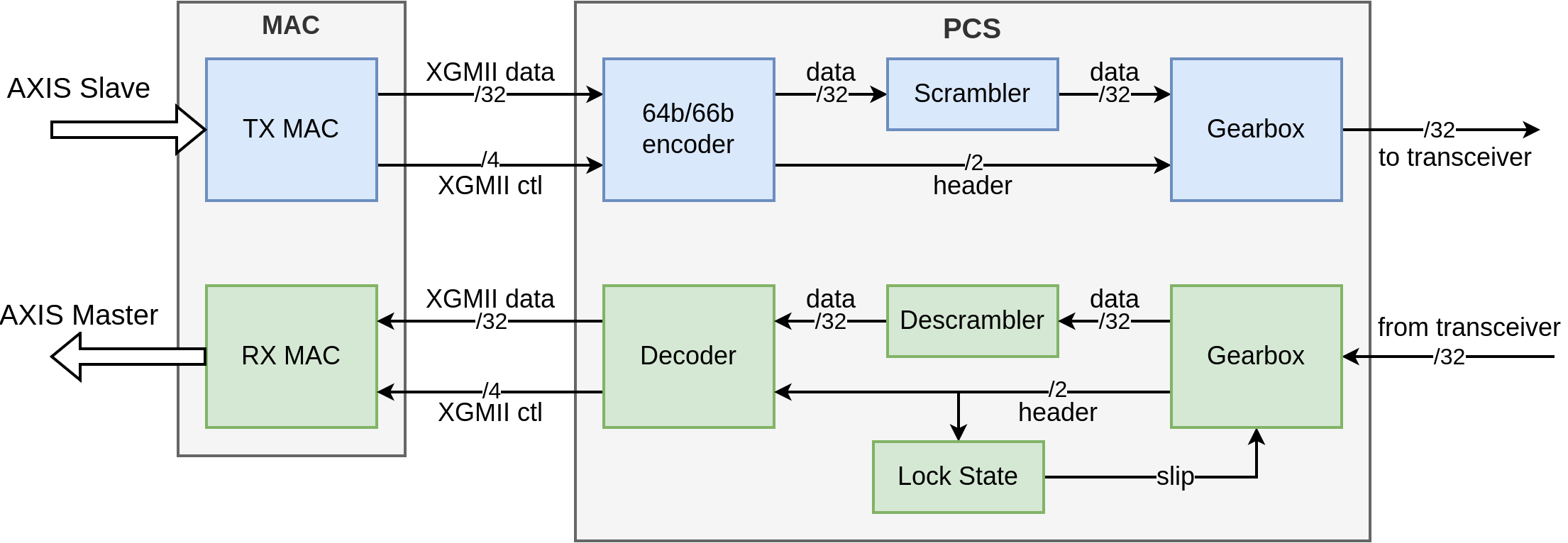
Figure 1: MAC/PCS Overview
There are two clock domains at ~322MHz, one for transmit and one for receive. Both Tx/Rx clocks are sourced from the transceivers external to this block. 322MHz might seem like an odd number but this is one of the key aspects for low latency operation, discussed further in Part 3
Verification
This was one area of the project I was most happy with as it gave me the opportunity to experiment with cocotb and pyuvm. cocotb is a testbench environment for verifying RTL using Python. As a regular Python user, this really appealed to me, mainly as Python is a far more expressive and capable language than SystemVerilog. Additionally, having previously used UVM and seen first-hand the benefits of constrained random stimulus, I was keen to see how pyuvm compared with a traditional setup.
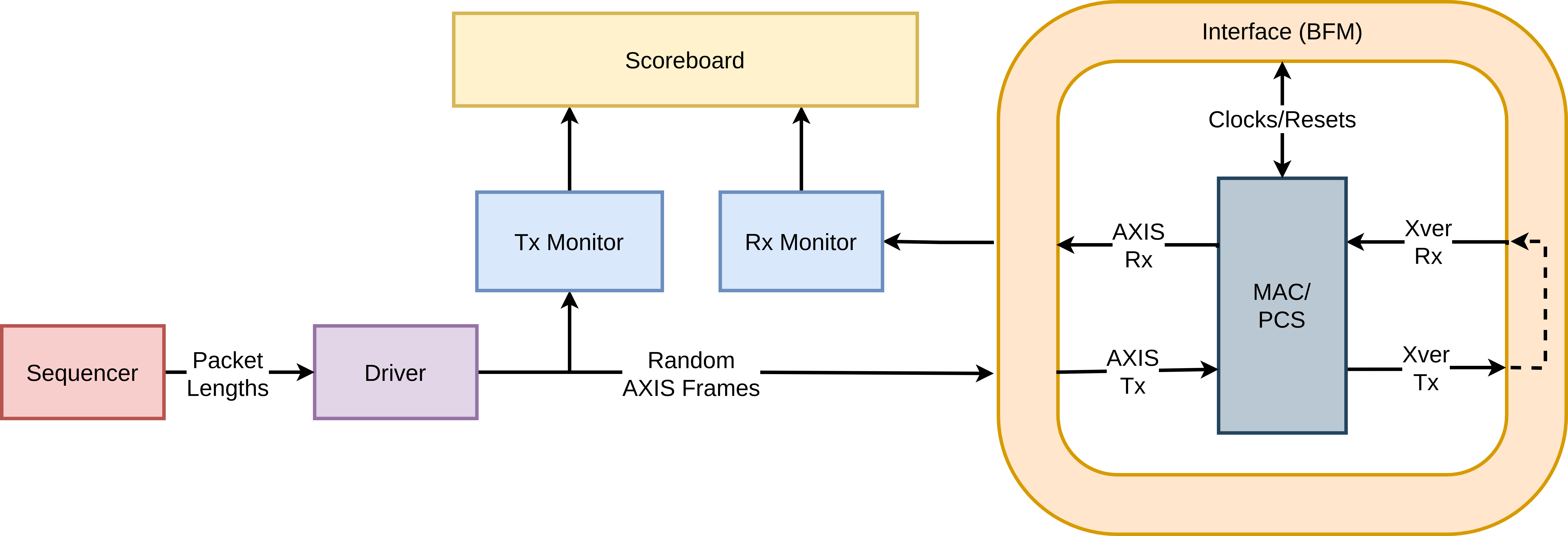
Figure 2: Testbench Overview
The testbench works as follows:
- The Sequencer generates a random packet length from a uniform distribution.
- The Driver creates an AXIS frame with random data with length from the Sequencer.
- The Tx Monitor captures the random frame and passes it to the Scoreboard.
- The BFM (Bus Functional Model) interacts with the DUT (Device Under Test), in this case the MAC/PCS. This sets up clocks and resets, and applies/captures the AXIS interfaces. Additionally, it connects the transceiver interface in loopback with an optional bit or cycle delay.
- The Rx Monitor monitors the received AXIS frames and passes it to the Scoreboard.
- The Scoreboard checks the data in transmitted/received frames for equality and that the CRC valid flag was set for the received frame.
While testing in loopback is clearly less robust than with packet generation and checking on both sides, it proved incredibly useful for development and was suitable for the goals of this project.
Icarus Verilog is used as the simulator, as I wanted to use something open-source. I did get the latest version of Verilator working with cocotb, however there is an unresolved (at the time of writing) issue with the AXIS source/monitor package used (#3919). Verilator would have enabled the collection of code coverage which is useful for exposing areas in the design not stimulated by the testbench.
The testbench can be run in multiple configurations (including module parameter overrides) with pytest, which allows for integration with CI/CD workflows and is demonstrated in the GitHub repository.
Ethernet Core and Example Design
An overview of the complete Ethernet core and example design is below. The core combines the MAC/PCS and the generated GTY IP with some wrapper code for initialisation.
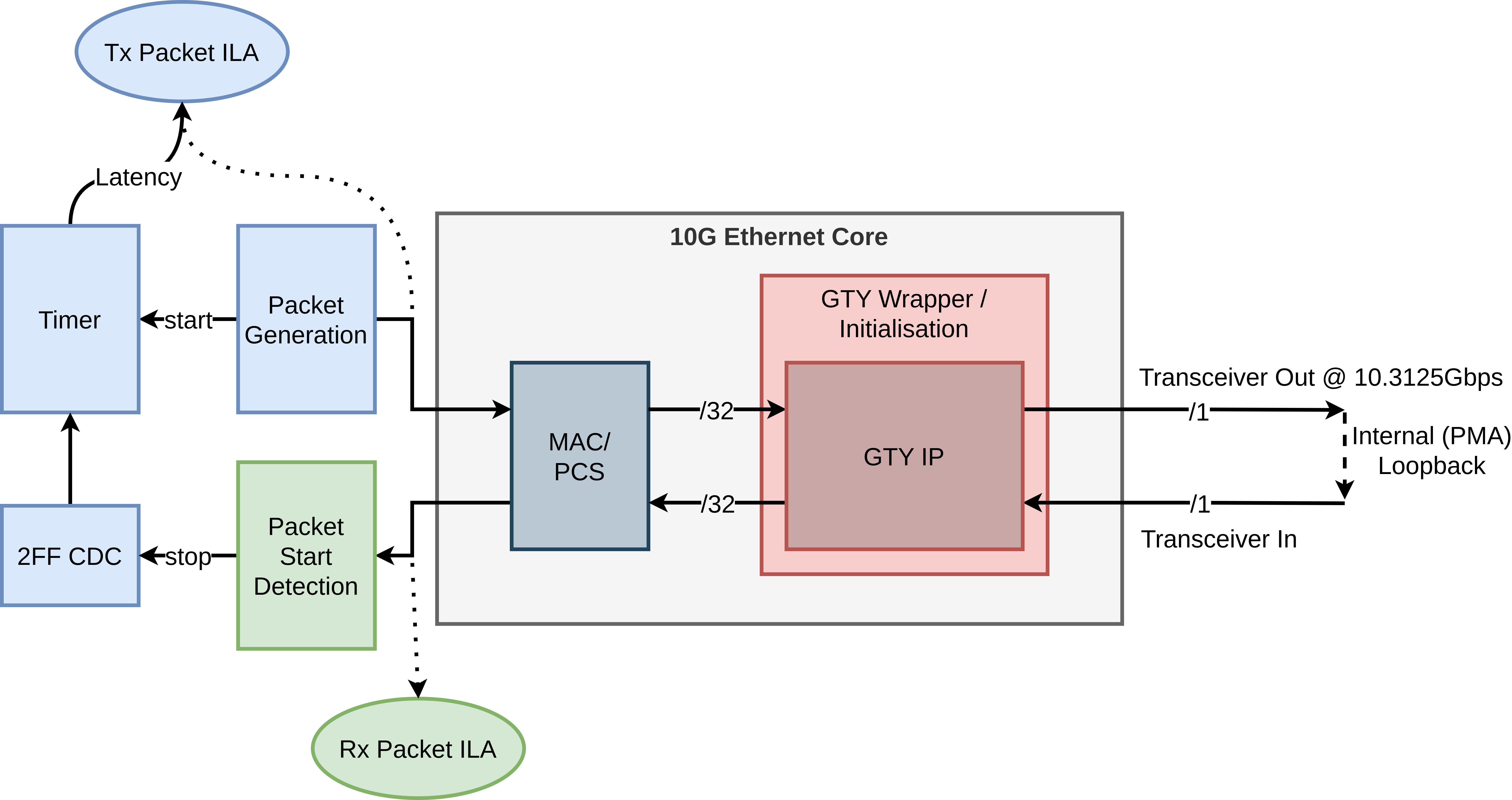
Figure 3: Example Design Overview
The example design brings up the core, generates test packets and and measures the latency between the start of the transmitted frames and start of received frames. This will be discussed further in Part 4 - Performance Measurement and Comparison
Next Post - Low Latency Techniques